Embedded PWM Driver
For one of my robotics projects I needed to turn an
antenna from side-to-side. So I pulled out my servos, breadboard, 555
timer, assorted gates, resistors, caps, and other crap to start putting
together a driver. I've probably did this dozens of times over the
years. As I was looking through the bins of assorted electronics stuff
I found my box of uContollers. At that point the 'duh' light goes on.
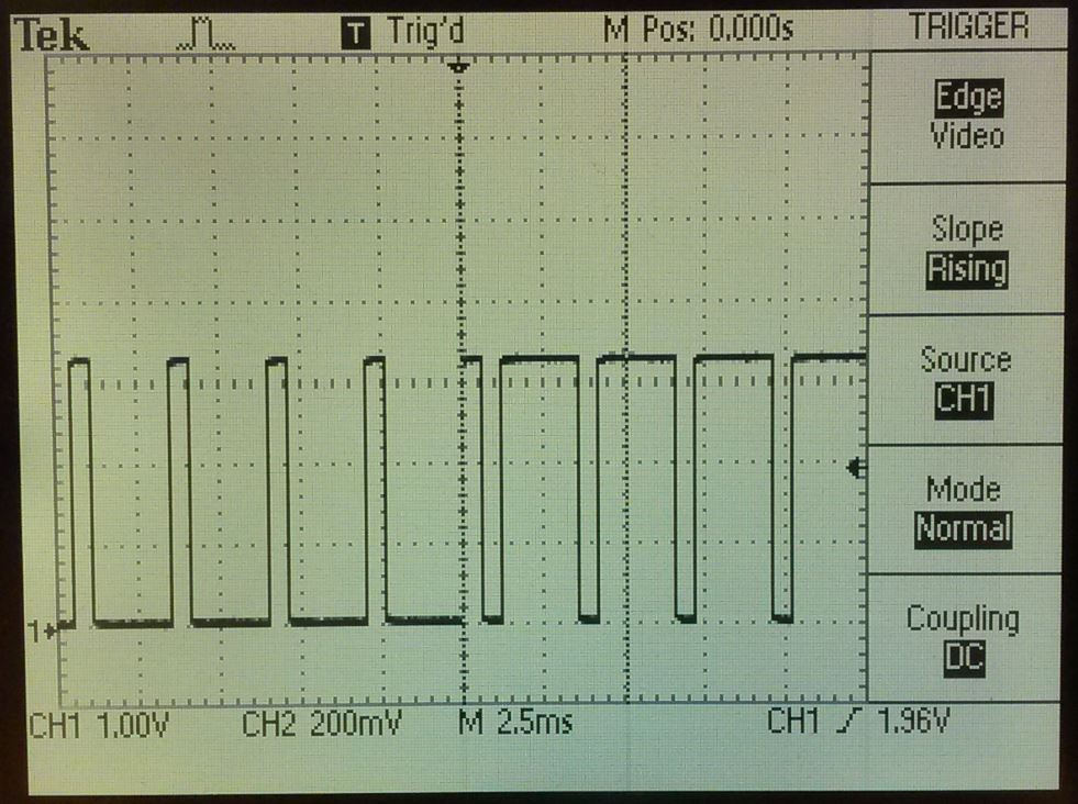
 Pulse
Width Modulation (PWM) is a form of signal modulation where the widths or
pulses correspond to specific data values. For servos, the different
pulse widths would correspond to different positions of the servo. The
picture below (right) shows the pulse train going to the servo. The
period (1/freq) is about 3mS or a 333Hz pulse train. This frequency will vary
depending on the servos you are using but most are in the hundreds of Hz
to lower Khz range. There is usually a dead-band at both extremes,
maybe less than 5% and greater than 95%. Here no change will happen.
If a PWM signal with a 50% duty cycle were sent the servo would go to its
180 degree position. A 5% duty cycle may send it to 20 degrees and 95% to
340 degree. The ratios and actual positions depends on the servos.
Pulse
Width Modulation (PWM) is a form of signal modulation where the widths or
pulses correspond to specific data values. For servos, the different
pulse widths would correspond to different positions of the servo. The
picture below (right) shows the pulse train going to the servo. The
period (1/freq) is about 3mS or a 333Hz pulse train. This frequency will vary
depending on the servos you are using but most are in the hundreds of Hz
to lower Khz range. There is usually a dead-band at both extremes,
maybe less than 5% and greater than 95%. Here no change will happen.
If a PWM signal with a 50% duty cycle were sent the servo would go to its
180 degree position. A 5% duty cycle may send it to 20 degrees and 95% to
340 degree. The ratios and actual positions depends on the servos.
The coding of the uController is pretty straight forward. Basically
you need to create a real time delay using the uController on-board crystal
or timer. I set mine up for 1uSec increments. The rest is just
shifting in 1s or 0s into the register which cooresponds to the desired
output pin. The Atmel MEGA-1284P demo board I used just happens to
have an LED wired to the same output register. Code snippet below.
I will note you need to be careful how you write the code. Remember,
the servo will go to and stop at a position but you need to continuously send
the PWM signal. If the pulse train stops like when a delay or
interrupt is sent the servo will slip back if torqued. One of the
simple ways to code is just to know the position-to-position travel time and
add the extra time needed in the loop. The snippet below drives the
servo to a position and allows for it to stay in that position for 1sec.
Why not just use a uController?!?! After all, these are the kinds of
applications they were designed for. Years of conditioning makes you
want to grab wire and a breadboard but here we have a programmable solution
all in one chip.
To begin with, a servo (or servomotor) is an error-sensing, error-correcting
motor. They're a digital / analog hybrid containing a motor and either
a potentiometer for position sensing or an encoder which provides both speed
and positioning using proportional integral derivative (PID). Most
servos have a less than 360 degree rotation (but not always) and are driven
using pulse width modulation (PWM).
Embebbed
PWM Driver
PWM Generator - Source
Code
A lot easier than the breadboard
route.